Located outside the village of Kilmacthomas, Co Waterford, brothers Noel and Ger Hickey are the men behind the patented Safeshaft System. For those unfamiliar with Safeshaft, it’s essentially a hydraulic drive system which replaces the conventional PTO shaft used to power vacuum pumps on slurry tankers.
Noel is an agricultural mechanic running his own business while Ger runs his own metal fabrication shop. In 2015, the brothers were approached by a neighbour to see if they could design a solution to replace the standard PTO shaft on his slurry tanker. The duo got to work.
After several months trying different solutions, the brothers found one they felt would work. It was just a matter of sourcing suitable components.
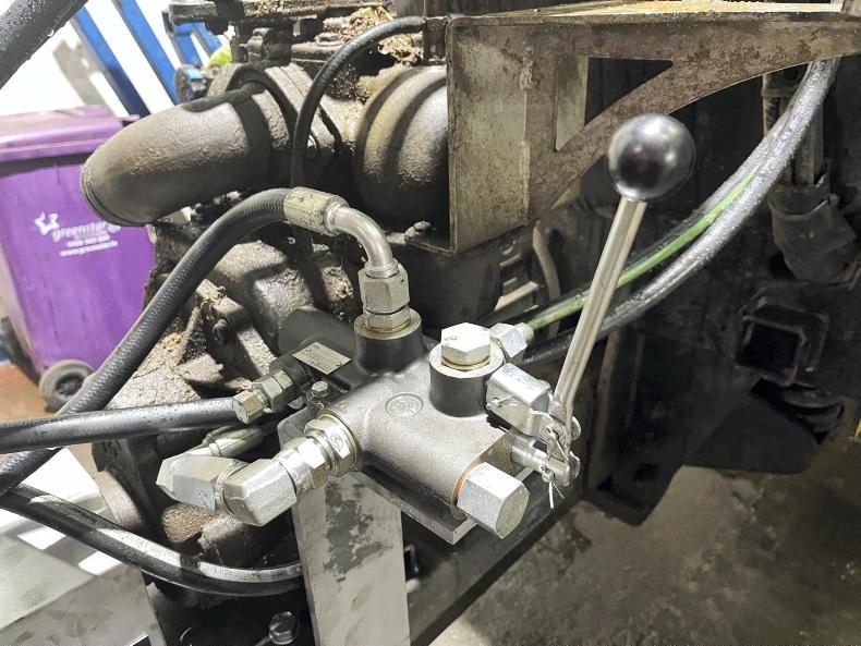
The manual shut-off lever is designed to stop the vacuum pump at ground level.
Both the brothers’ backgrounds provided great expertise for the task in hand. Noel’s hands-on knowledge of agricultural machinery combined with Ger’s engineering knowledge and fabrication left tweaking and testing much easier. A prototype was developed and tested by local contractor PJ Mullhearne, who tested it over the summer months to find any potential issues or flaws with the design.
Design
What you see with the Safeshaft is what you get. The concept is to remove the PTO shaft, transferring the drive from the tractor’s PTO to the tanker’s pump.
Obviously, this is the most dangerous part of the slurry tanker, which is due to its high speed of rotation (nine revolutions per second) and close proximity to people.

Numerous base plates are available to suit different makes and models of vacuum pumps.
The Hickey brothers have fitted a hydraulic motor in place of the PTO shaft. This is powered by the tractor’s hydraulic system through a double-acting spool valve. The return line is fitted with a non-return valve to stop the pump being run in reverse accidentally. To allow the pump to start slowly and to prevent shock engagement and disengagement, an anti-cavitation block is fitted which alters the oil flow on start-up and stopping, making it smoother.
The power is transferred from the motor to the pump via a steel coupler with a shock absorber that can allow for up to 4° of misalignment and is fully guarded for safety.
Retrofit process
The Hickey brothers offer complete retrofit kits with the particular mounting plate to suit each tanker brand and the vacuum pump in question.
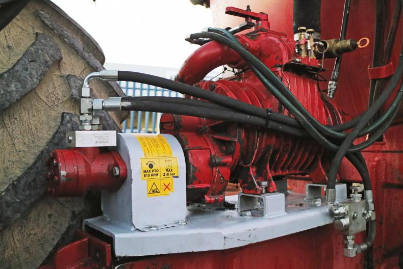
Depending on the brand of slurry tanker and pump, the pump may need to be moved rearwards or mounted crossways so that the hydraulic motor is out of reach of the tractor’s lift arms.
According to Noel, the fitment process takes as little as just one hour.

The steel spider type coupling has a plastic shock absorber.
1 For starters, the PTO shaft and PTO cover need to be removed. Next, the four bolts securing the vacuum pump to the tanker chassis need to be removed. Once these bolts are removed, the pump needs to be lifted upwards using a loader or similar.
2 Once there’s enough clearance, the new galvanised base plate specific to the particular pump needs to be slid into place and bolted down to the original mounting plate on the tanker’s chassis. Most base plates are also designed to be mounted crossways on the drawbar if desired. Either way, these bolts need to be tightened correctly.
3 The next step is to seat the pump in position on the new base plate. Fasten the bracket to the face of the pump using the holes in the bracket which correspond with the holes on the face of the pump previously used for mounting the PTO guard. Longer bolts than the previous PTO guard bolts may be needed.
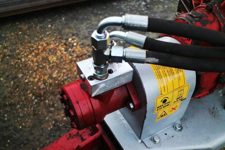
An anti-cavitation block is fitted which alters oil flow allowing the vacuum pump to engage and disengage smoothly.
4 Next up, the hydraulic motor and coupler needs to be placed on to the pump shaft and mounted to the front plate with the anti-cavitation valve facing upwards. Once the motor has been fastened to the front plate, square the vacuum pump up on the new base plate and fasten the pump via the four bolts.
5 When the pump and base plate is fastened, tighten the coupler’s hex bolts on both the vacuum pump and hydraulic motor side. At this stage the parking brake will need to be fitted which will involve drilling the base plate to suit the particular bracket.
6 Although the pipe work comes readymade, it needs to be plumbed. Where a hose arm is fitted, try to route the flow and return pipes so that they are alongside existing hydraulic hoses. If fitted with the shut-off valve, make sure pipe work is plumbed according to the diagram provided. It is essential that the one-way valve is fitted on the return line to prevent the pump being operated in reverse.
The manual shut-off lever is designed to stop the vacuum pump at ground level. Once engaged, oil is diverted back through the return causing the pump to cut out. When the spool has been re-engaged, the lever will automatically return to its working position.
Functionality
The system brings about several notable advantages. Firstly, and most obviously, it removes the dangers associated with a PTO shaft.
Secondly, it cuts out the possibility of damaging an expensive wide-angle PTO shaft with the lift arms. This also means the tractor can turn tighter against the tanker’s drawbar.

The Danfoss hydraulic motor has a hydraulic flow requirement of 28l/min.
Finally, it means the tanker does not have to be straight when filling in the yard, and the hydraulic pump can be left running on the headlands.
Not limited to tankers
The brothers currently have over 70 units to date working throughout Ireland and the UK. It’s worth noting that this design isn’t solely limited to slurry tankers, but can also be fitted to PTO powered implements which do not require huge amounts of power to drive. One such example is sprayers, which the Hickeys have a number of hydraulic drives fitted too.
Hydraulic requirement
The big question some readers will have is what is the hydraulic requirement, and will I have enough capacity to simultaneously run both the hydraulic pump and the macerator on a low-emission slurry spreading (LESS) system. According to the Hickeys, when filling the tanker, the system needs 28 l/min, while to spread it needs 20 l/min.

Ger and Noel Hickey.
In terms of running a macerator, most will work on 30-35 l/min. This means total oil flow will be in the region of 50-60 l/min, which would be within the capability of the vast majority of tractors which are given the task of operating a tanker and LESS system.
Cost
The Safeshaft system was grant-approved several years ago. Although the list of approved equipment under the new TAMS has yet to be released, it’s expected that the system once again will be eligible once supplied with the shut-off valve.
The Hickeys explained that they cater for all tanker manufacturers, with kits on the shelf ready for delivery. Depending on the tanker, there are numerous options available to suit individual requirements, such as manual or electric flow control valves, in-cab speed display and in-line filters.
The patented system comes with a manufacturer’s warranty and units are CE marked. The system can be used with all tractor types including low- and high-oil-flow systems.
The retrofit kit is available as two options. Option one is the base kit which is priced at €1,200 plus VAT, and option two comes with a shut-off valve. To be eligible for grant aid, the unit has to be fitted with the shut-off valve. This comes at a slightly higher price of €1,500 plus VAT.
Depending on brand, a new standard shaft will cost in the region of €250-280 while a wide-angle shaft will cost somewhere in the region of €650. Most slurry tankers will require at least one replacement shaft throughout their lifetime.
Located outside the village of Kilmacthomas, Co Waterford, brothers Noel and Ger Hickey are the men behind the patented Safeshaft System. For those unfamiliar with Safeshaft, it’s essentially a hydraulic drive system which replaces the conventional PTO shaft used to power vacuum pumps on slurry tankers.
Noel is an agricultural mechanic running his own business while Ger runs his own metal fabrication shop. In 2015, the brothers were approached by a neighbour to see if they could design a solution to replace the standard PTO shaft on his slurry tanker. The duo got to work.
After several months trying different solutions, the brothers found one they felt would work. It was just a matter of sourcing suitable components.
The manual shut-off lever is designed to stop the vacuum pump at ground level.
Both the brothers’ backgrounds provided great expertise for the task in hand. Noel’s hands-on knowledge of agricultural machinery combined with Ger’s engineering knowledge and fabrication left tweaking and testing much easier. A prototype was developed and tested by local contractor PJ Mullhearne, who tested it over the summer months to find any potential issues or flaws with the design.
Design
What you see with the Safeshaft is what you get. The concept is to remove the PTO shaft, transferring the drive from the tractor’s PTO to the tanker’s pump.
Obviously, this is the most dangerous part of the slurry tanker, which is due to its high speed of rotation (nine revolutions per second) and close proximity to people.
Numerous base plates are available to suit different makes and models of vacuum pumps.
The Hickey brothers have fitted a hydraulic motor in place of the PTO shaft. This is powered by the tractor’s hydraulic system through a double-acting spool valve. The return line is fitted with a non-return valve to stop the pump being run in reverse accidentally. To allow the pump to start slowly and to prevent shock engagement and disengagement, an anti-cavitation block is fitted which alters the oil flow on start-up and stopping, making it smoother.
The power is transferred from the motor to the pump via a steel coupler with a shock absorber that can allow for up to 4° of misalignment and is fully guarded for safety.
Retrofit process
The Hickey brothers offer complete retrofit kits with the particular mounting plate to suit each tanker brand and the vacuum pump in question.
Depending on the brand of slurry tanker and pump, the pump may need to be moved rearwards or mounted crossways so that the hydraulic motor is out of reach of the tractor’s lift arms.
According to Noel, the fitment process takes as little as just one hour.
The steel spider type coupling has a plastic shock absorber.
1 For starters, the PTO shaft and PTO cover need to be removed. Next, the four bolts securing the vacuum pump to the tanker chassis need to be removed. Once these bolts are removed, the pump needs to be lifted upwards using a loader or similar.
2 Once there’s enough clearance, the new galvanised base plate specific to the particular pump needs to be slid into place and bolted down to the original mounting plate on the tanker’s chassis. Most base plates are also designed to be mounted crossways on the drawbar if desired. Either way, these bolts need to be tightened correctly.
3 The next step is to seat the pump in position on the new base plate. Fasten the bracket to the face of the pump using the holes in the bracket which correspond with the holes on the face of the pump previously used for mounting the PTO guard. Longer bolts than the previous PTO guard bolts may be needed.
An anti-cavitation block is fitted which alters oil flow allowing the vacuum pump to engage and disengage smoothly.
4 Next up, the hydraulic motor and coupler needs to be placed on to the pump shaft and mounted to the front plate with the anti-cavitation valve facing upwards. Once the motor has been fastened to the front plate, square the vacuum pump up on the new base plate and fasten the pump via the four bolts.
5 When the pump and base plate is fastened, tighten the coupler’s hex bolts on both the vacuum pump and hydraulic motor side. At this stage the parking brake will need to be fitted which will involve drilling the base plate to suit the particular bracket.
6 Although the pipe work comes readymade, it needs to be plumbed. Where a hose arm is fitted, try to route the flow and return pipes so that they are alongside existing hydraulic hoses. If fitted with the shut-off valve, make sure pipe work is plumbed according to the diagram provided. It is essential that the one-way valve is fitted on the return line to prevent the pump being operated in reverse.
The manual shut-off lever is designed to stop the vacuum pump at ground level. Once engaged, oil is diverted back through the return causing the pump to cut out. When the spool has been re-engaged, the lever will automatically return to its working position.
Functionality
The system brings about several notable advantages. Firstly, and most obviously, it removes the dangers associated with a PTO shaft.
Secondly, it cuts out the possibility of damaging an expensive wide-angle PTO shaft with the lift arms. This also means the tractor can turn tighter against the tanker’s drawbar.
The Danfoss hydraulic motor has a hydraulic flow requirement of 28l/min.
Finally, it means the tanker does not have to be straight when filling in the yard, and the hydraulic pump can be left running on the headlands.
Not limited to tankers
The brothers currently have over 70 units to date working throughout Ireland and the UK. It’s worth noting that this design isn’t solely limited to slurry tankers, but can also be fitted to PTO powered implements which do not require huge amounts of power to drive. One such example is sprayers, which the Hickeys have a number of hydraulic drives fitted too.
Hydraulic requirement
The big question some readers will have is what is the hydraulic requirement, and will I have enough capacity to simultaneously run both the hydraulic pump and the macerator on a low-emission slurry spreading (LESS) system. According to the Hickeys, when filling the tanker, the system needs 28 l/min, while to spread it needs 20 l/min.
Ger and Noel Hickey.
In terms of running a macerator, most will work on 30-35 l/min. This means total oil flow will be in the region of 50-60 l/min, which would be within the capability of the vast majority of tractors which are given the task of operating a tanker and LESS system.
Cost
The Safeshaft system was grant-approved several years ago. Although the list of approved equipment under the new TAMS has yet to be released, it’s expected that the system once again will be eligible once supplied with the shut-off valve.
The Hickeys explained that they cater for all tanker manufacturers, with kits on the shelf ready for delivery. Depending on the tanker, there are numerous options available to suit individual requirements, such as manual or electric flow control valves, in-cab speed display and in-line filters.
The patented system comes with a manufacturer’s warranty and units are CE marked. The system can be used with all tractor types including low- and high-oil-flow systems.
The retrofit kit is available as two options. Option one is the base kit which is priced at €1,200 plus VAT, and option two comes with a shut-off valve. To be eligible for grant aid, the unit has to be fitted with the shut-off valve. This comes at a slightly higher price of €1,500 plus VAT.
Depending on brand, a new standard shaft will cost in the region of €250-280 while a wide-angle shaft will cost somewhere in the region of €650. Most slurry tankers will require at least one replacement shaft throughout their lifetime.


SHARING OPTIONS